Resistance welding is a group of welding processes whereby metals are joined together by the heat obtained from resistance to the flow of electric current and by the application of pressure. One of the most distinguishing features of resistance welding is that no filler metal is needed, unlike MIG, Stick and TIG.
Contents
Advantages of Resistance Welding
- Fast rate of production.
- No filler metal is needed.
- Semi automatic equipment.
- Both similar and dissimilar metals can be welded.
- High reliability and reproducibility are obtained.
- More general elimination of warping or distortion of parts
- Low welding fumes, more environmentally friendly than many other welding processes
Disadvantages of Resistance Welding
- The initial cost of equipment is high.
- Skilled persons are needed for the maintenance of equipment and its controls.
- In some materials, special surface preparation is required.
- Bigger job thicknesses cannot be welded.
Common Applications of Resistance Welding
- Joining sheets, bars, rods and tubes.
- Making tubes and metal furniture.
- (Welding aircraft and automobile parts.
- Making cutting tools.
- Making fuel tanks of cars, tractors etc.
- Making wire fabric, grids, grills, mash weld, containers etc.
Types of Resistance Welding
There are different types of resistance welding such as seam welding, spot welding and butt welding. Each process is suited to different applications. The most common methods of resistance welding are:
- Spot Welding (RSW)
- Seam Welding (RSEW)
- Upset Butt Welding (UW)
- Flash Butt Welding (FW)
- Projection Welding (PW)
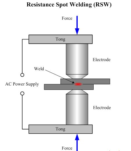
Resistance Spot Welding
Spot welding is a resistance welding process in which overlapping sheets are joined by local fusion at one or more spots by the heat generated and resistance to the flow of electric current through workpieces that are held together under force by two electrodes, One electrode is placed above and the other below the two overlapping sheets.
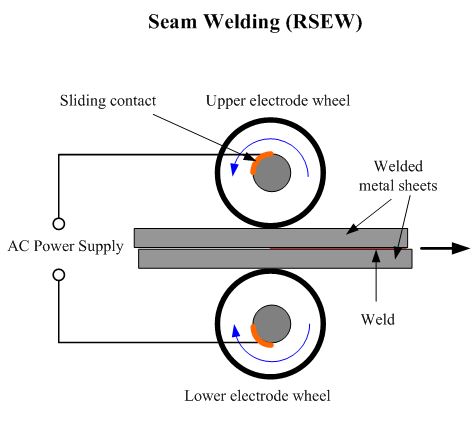
Resistance Seam Welding
Seam welding is a resistance welding process which is a variation of resistance spot welding. The metals are joined together by the heat obtained from resistance to electric current (flow) through work parts that are held together under pressure by electrodes. The circular electrodes rotate to form a series of overlapping resistance spot welds made progressively along a joint to make a continuous welded seam.
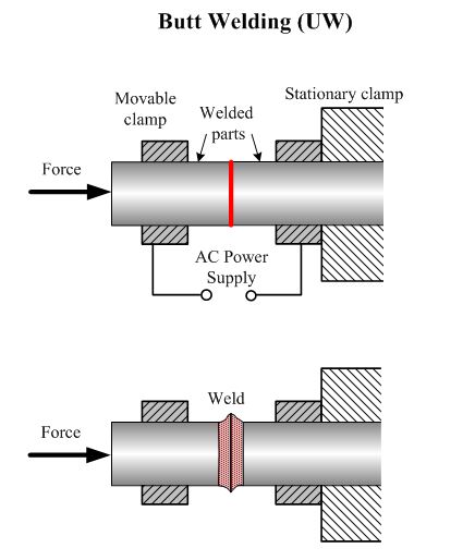
Resistance Upset Butt Welding
Upset butt welding is a resistance welding process wherein metals are joined over the entire area of abutting surfaces by the heat obtained from the resistance to electric current through the area of contact of those surfaces.
Pressure is applied before heating is started and is maintained throughout the heating period. This pressure or force is later on increased to give a forging squeeze when the welding temperature* has been reached. When sufficient upset has been produced, the welding current is cut off and the force is removed.
In upset welding no arcing (and hence flashing) takes place between the surfaces being joined. Heat is produced solely by the electrical resistance at the abutting surfaces due to the passage of an electrical current.
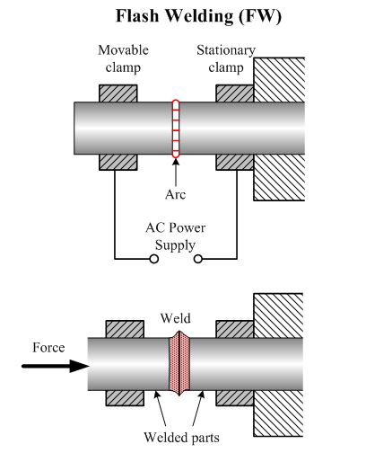
Flash Butt Welding
Flash butt welding is a resistance welding process wherein metals are joined over the entire area of abutting surfaces, by the heat obtained from resistance to electric current between the two surfaces, and by the application of pressure after heating is substantially completed.
In flash welding heat application precedes the pressure whereas in butt welding constant pressure is applied during the heating process which eliminates flashing.
Flashing and upsetting are accompanied by expulsion of metal from the joint.
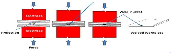
Resistance Projection Welding
Projection welding is a resistance welding process in which metals are joined together by the heat from resistance to electric current through work parts held together under pressure by electrodes. The welds are localized at predetermined points such as raised ‘projections’ on the surface of the metal.
Fundamentals of Electric Resistance Welding
The two factors or variables mainly responsible for resistance welding are:
- The generation of heat at the place where two pieces are to be joined.
- The application of pressure at the place where a weld joint is to be formed.
Heat
The heat, H, for electrical resistance welding is generated by passing a large electrical current (of the order of 3000 to 100,000 Amps with a voltage between 1 and 25 volts) through two pieces of metal that are touching each other. It will follow there formula:
H α I2RT
Where:
- H is the heat generate Indicate In joules,
- I is the current in root mean square amperes,
- R is the resistance in ohms,
- T is the time (from fraction of a second to a few seconds) of current flow through the pieces to be welded.
Current (I)
With other parameters kept constant, the temperature in resistance welding is regulated by controlling the magnitude and timing of the welding current. Enough welding current is required to heat the metal pieces being welded to their plastic state.
The current is obtained from a step down transformer. The magnitude of current may be Controlled through taps on the primary of the transformer or by an autotransformer that varies the primary voltage supplied to the main transformer.
Low welding current does not provide proper fusion whereas if welding current is too high, the entire thickness of the work metal between the electrodes is heated to the plastic state by the time the weld zone reaches the fusion temperature, and the electrodes embed themselves deeply into the metal.
As the current/current density is increased, the weld time can be decreased sufficiently to produce a weld without overheating the electrode contact surfaces. As the welding current increases, the nugget diameter, breaking load of welded joint and the electrode indentation into the workpieces, all, increase. In resistance welding, three types of current supply systems generally are used
- AC systems.
- DC systems.
- Stored energy current systems.
By far the majority of resistance welding machines operate on single phase alternating current of the power line frequency, usually 50 cycles second. A single phase transformer converts the power line voltage to a low voltage and provides the high currents needed for welding.
High frequency resistance welding is used for applications of continuous seam or butt seam welding. The welding current frequencies are of the order of 450,000 cycles per second. In DC systems, energy is delivered directly from the power line and rectifier to direct current on the secondary side of the welding transformer.
Stored energy systems are: storage batteries, electromagnetic type, the homopolar generator and capacitor type. Capacitor stored-energy type involves charging a group of capacitors from a high-voltage rectifier unit and subsequent discharge of the energy from the capacitors through a welding transformer.
Resistance (R)
The total resistance of the system between the electrodes consists of:
- The resistance of the workpiece (R1*)
- The contact resistance between the electrodes and the work (R2*)
- The resistance between the faying surfaces of the two metal pieces to be welded together (R3*)
In order to obtain a sound weld and to avoid overheating of the welding electrodes, R1 and R2 should be kept as low as possible with respect to resistance R3.
* R1, the resistance of the workpiece, depends upon the nature of the material and its thickness. It cannot be changed otherwise. If the workpiece material has low electrical resistance, such as aluminium, it requires very high currents in order to produce the required welding temperature and hence a proper weld.
* R2, the contact resistance between the electrode and the workpiece can be minimized by:
- Keeping the electrode tip and the workpiece surface properly cleaned.
- Using the welding electrodes of highly conductive materials such as Cu-Cd or Cu-Cr alloys.
- Controlling the shape and size of the electrodes.
- Using the proper pressure between the electrodes and the workpieces.
* R3, the resistance between the contacting surfaces of the two workpieces, varies with the quality of the surfaces. Surfaces that have not been cleaned and possess scale, dirt or other contaminants on them offer more resistance to the flow of welding current.
Smooth workpiece surfaces and high electrode pressures reduce resistance RJ. Overheating of the welding electrodes is avoided by circulating either water or a refrigerant through them. The main aim is to obtain a sound weld without overheating either the electrodes or the workpieces.
Time (T)
Four definite segments or periods of timing are set up on a resistance spot welding machine during one welding cycle
- Squeeze time.
- Weld time.
- Hold time.
- Off time.
Squeeze time. It is the time between the initial application of the electrode pressure on the work and the initial application of current to make the weld. During this period the upper electrode comes in contact with the workpiece and develops full electrode force. At the end of the squeeze time, the welding current is applied.
Weld time. During this period the welding current flows through the circuit, i.e., it enters from one electrode, passes through the work pieces and goes out from the second electrode.
Hold time. It is the time during which force acts at the point of welding after the last impulse of welding current ceases. The electrode pressure is maintained until the metal has somewhat cooled.
Off time. It is the interval from the end of the hold time to the beginning of the squeeze time for the next (resistance) welding cycle.
In automatic machines all these segments of times are controlled / automatically whereas in manually operated machines, only the weld time is controlled automatically and the remaining time periods are adjusted by the operator himself.
Weld time can be controlled automatically by using a suitable (electronic) timer. Weld times range from one-half cycle of 50 cycle frequency for thinnest sheets to as long as several seconds for thicker plates, depending somewhat upon the metal being welded.
There are a number of types of spot welding cycles which incorporate different elements. Some of them are explained below:
- Just before the weld time the electrode pressure is reduced a little in order to intentionally increase the resistance between the faying surfaces of the workpieces. This will help raise temperature quickly at the place of welding.
- During the Hold Time, electrode pressure is increased in order to forge the weld metal as it cools. This will improve weld strength.
- Post heat current is applied along with the forge pressure. This cycle, the welding force usually is maintained until the post heat current is applied after which it is increased to the forging force. Such a cycle is used chiefly for grain refinement on carbon and alloy steels and is not used on low carbon steels.
Pressure or Electrode Force
Electrode force is the force applied to the workpieces by the electrodes during the welding cycle. Pressure exerted on the workpieces by the welding electrodes does the following:
- It brings the various interfaces into intimate contact and thus affects the contact resistance between the two workpieces.
- It ensures the completion of the electrical circuit between the electrodes and through the work.
- It permits the weld to be made at lower temperatures.
- It provides a forging action and thus reduces weld porosity.
If too little electrode force is used, the contact resistance between the two workpieces is high and surface burning and pitting of the electrodes may result.
If too high electrode force is used, it decreases the contact resistance of the work metal and therefore reduces the total heat generated between the faying surfaces of the workpieces by the welding current.
Too high electrode force may, also, squeeze softened hot metal between the faying surfaces or the work may be indented by the electrodes. Pressure on the workpieces is exerted by the electrodes extending from the arms of the welding machine. Besides this, the other junctions performed by electrodes are
- They carry the current which passes through and generates heat at the place where the two workpiece are in pressed contact.
- Depending upon the area of the electrodes face or tip, they determine the current density in the weld zone.
- They dissipate the heat from the weld zone and thus prevent surface fusion of the work